In the dynamic evolution of AI and cloud computing, the deployment of efficient and reliable hardware is critical. As we roll out our Gen 12 hardware across hundreds of cities worldwide, the challenge of maintaining optimal thermal performance becomes essential. This blog post provides a deep dive into the robust thermal design that supports our newest Gen 12 server hardware, ensuring it remains reliable, efficient, and cool (pun very much intended).
The importance of thermal design for hardware electronics
Generally speaking, a server has five core resources: CPU (computing power), RAM (short term memory), SSD (long term storage), NIC (Network Interface Controller, connectivity beyond the server), and GPU (for AI/ML computations). Each of these components can withstand different temperature limits based on their design, materials, location within the server, and most importantly, the power they are designed to work at. This final criteria is known as thermal design power (TDP).
The reason why TDP is so important is closely related to the first law of thermodynamics, which states that energy cannot be created or destroyed, only transformed. In semiconductors, electrical energy is converted into heat, and TDP measures the maximum heat output that needs to be managed to ensure proper functioning.
Back in December 2023, we talked about our decision to move to a 2U form factor, doubling the height of the server chassis to optimize rack density and increase cooling capacity. In this post, we want to share more details on how this additional space is being used to improve performance and reliability supporting up to three times more total system power.
Standardization
In order to support our multi-vendor strategy that mitigates supply chain risks ensuring continuity for our infrastructure, we introduced our own thermal specification to standardize thermal design and system performance. At Cloudflare, we find significant value in building customized hardware optimized for our unique workloads and applications, and we are very fortunate to partner with great hardware vendors who understand and support this vision. However, partnering with multiple vendors can introduce design variables that Cloudflare then controls for consistency within a hardware generation. Some of the most relevant requirements we include in our thermal specification are:
Ambient conditions: Given our globally distributed footprint with presence in over 330 cities, environmental conditions can vary significantly. Hence, servers in our fleet can experience a wide range of temperatures, typically ranging between 28 to 35°C. Therefore, our systems are designed and validated to operate with no issue over temperature ranges from 5 to 40°C (following the ASHRAE A3 definition).
Thermal margins: Cloudflare designs with clear requirements for temperature limits on different operating conditions, simulating peak stress, average workloads, and idle conditions. This allows Cloudflare to validate that the system won’t experience thermal throttling, which is a power management control mechanism used to protect electronics from high temperatures.
Fan failure support to increase system reliability: This new generation of servers is 100% air cooled. As such, the algorithm that controls fan speed based on critical component temperature needs to be optimized to support continuous operation over the server life cycle. Even though fans are designed with a high (up to seven years) mean time between failure (MTBF), we know fans can and do fail. Losing a server’s worth of capacity due to thermal risks caused by a single fan failure is expensive. Cloudflare requires the server to continue to operate with no issue even in the event of one fan failure. Each Gen 12 server contains four axial fans providing the extra cooling capacity to prevent failures.
Maximum power used to cool the system: Because our goal is to serve more Internet traffic using less power, we aim to ensure the hardware we deploy is using power efficiently. Great thermal management must consider the overall cost of cooling relative to the total system power input. It is inefficient to burn power consumption on cooling instead of compute. Thermal solutions should look at the hardware architecture holistically and implement mechanical modifications to the system design in order to optimize airflow and cooling capacity before considering increasing fan speed, as fan power consumption proportionally scales to the cube of its rotational speed. (For example, running the fans at twice (2x) the rotational speed would consume 8x more power,)
System layout
Placing each component strategically within the server will also influence the thermal performance of the system. For this generation of servers, we made several internal layout decisions, where the final component placement takes into consideration optimal airflow patterns, preventing pre-heated air from affecting equipment in the rear end of the chassis.
Bigger and more powerful fans were selected in order to take advantage of the additional volume available in a 2U form factor. Growing from 40 to 80 millimeters, a single fan can provide up to four times more airflow. Hence, bigger fans can run at slower speeds to provide the required airflow to cool down the same components, significantly improving power efficiency.
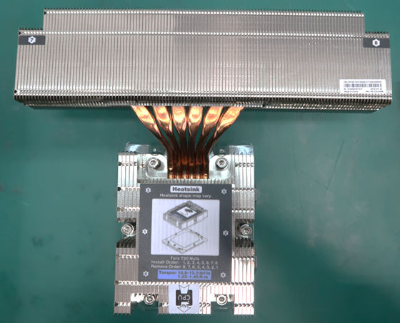
The Extended Volume Air Cooled (EVAC) heatsink was optimized for Gen 12 hardware, and is designed with increased surface area to maximize heat transfer. It uses heatpipes to move the heat effectively away from the CPU to the extended fin region that sits immediately in front of the fans as shown in the picture below.
EVAC heatsink installed in one of our Gen 12 servers. The extended fin region sits right in front of the axial fans. (Photo courtesy of vendor.)
The combination of optimized heatsink design and selection of high-performing fans is expected to significantly reduce the power used for cooling the system. These savings will vary depending on ambient conditions and system stress, but under a typical stress scenario at 25°C ambient temperature, power savings could be as much as 50%.
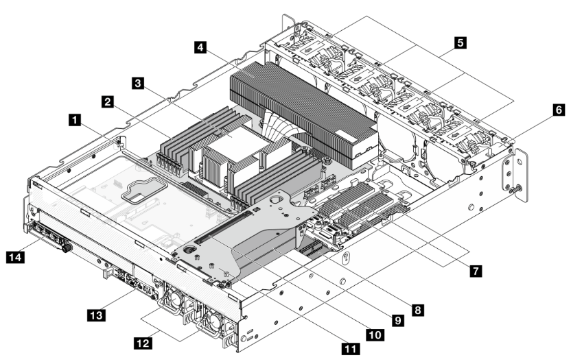
Additionally, we ensured that the critical components in the rear section of the system, such as the NIC and DC-SCM, were positioned away from the heatsink to promote the use of cooler available air within the system. Learning from past experience, the NIC temperature is monitored by the Baseboard Management Controller (BMC), which provides remote access to the server for administrative tasks and monitoring health metrics. Because the NIC has a built-in feature to protect itself from overheating by going into standby mode when the chip temperature reaches critical limits, it is important to provide air at the lowest possible temperature. As a reference, the temperature of the air right behind the CPU heatsink can reach 70°C or higher, whereas behind the memory banks, it would reach about 55°C under the same circumstances. The image below shows the internal placement of the most relevant components considered while building the thermal solution.
Using air as cold as possible to cool down any component will increase overall system reliability, preventing potential thermal issues and unplanned system shutdowns. That’s why our fan algorithm uses every thermal sensor available to ensure thermal health while using the minimum possible amount of energy.

Components inside the compute server from one of our vendors, viewed from the rear of the server. (Illustration courtesy of vendor.)
1️. Host Processor Module (HPM)
8. Power Distribution Board (PDB)
2️. DIMMs (x12)
9. GPUs (up to 2)
3️. CPU (under CPU heatsink)
10. GPU riser card
4. CPU heatsink
11. GPU riser cage
5. System fans (x4: 80mm, dual rotor)
12. Power Supply Units, PSUs (x2)
6. Bracket with power button and intrusion switch
13. DC-SCM 2.0 module
7. E1.S SSD
14. OCP 3.0 module
Making hardware flexible
With the same thought process of optimizing system layout, we decided to use a PCIe riser above the Power Supply Units (PSUs), enabling the support of up to 2x single wide GPU add-in cards. Once again, the combination of high-performing fans with strategic system architecture gave us the capability to add up to 400W to the original power envelope and incorporate accelerators used in our new and recently announced AI and ML features.
Hardware lead times are typically long, certainly when compared to software development. Therefore, a reliable strategy for hardware flexibility is imperative in this rapidly changing environment for specialized computing. When we started evaluating Gen 12 hardware architecture and early concept design, we didn’t know for sure we would be needing to implement GPUs for this generation, let alone how many or which type. However, highly efficient design and intentional due diligence analyzing hypothetical use cases help ensure flexibility and scalability of our thermal solution, supporting new requirements from our product teams, and ultimately providing the best solutions to our customers.
Rack-integrated solutions
We are also increasing the volume of integrated racks shipped to our global colocation facilities. Due to the expected increase in rack shipments, it is now more important that we also increase the corresponding mechanical and thermal test coverage from system level (L10) to rack level (L11).
Since our servers don’t use the full depth of a standard rack in order to leave room for cable management and Power Distribution Units (PDUs), there is another fluid mechanics factor that we need to consider to improve our holistic solution.
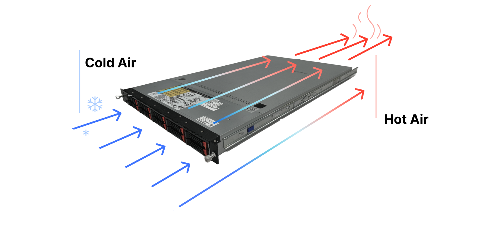
We design our hardware based on one of the most typical data center architectures, which have alternating cold and hot aisles. Fans at the front of the server pull in cold air from the corresponding aisle, the air then flows through the server, cooling down the internal components and the hot air is exhausted into the adjacent aisle, as illustrated in the diagram below.

A conventional air-flow diagram of a standard server where the cold air enters from the front of the server and hot air leaves through the rear side of the system.
In fluid dynamics, the minimum effort principle will drive fluids (air in this case) to move where there is less resistance — i.e. wherever it takes less energy to get from point A to point B. With the help of fans forcing air to flow inside the server and pushing it through the rear, the more crowded systems will naturally get less air than those with more space where the air can move around. Since we need more airflow to pass through the systems with higher power demands, we’ve also ensured that the rack configuration keeps these systems in the bottom of the rack where air tends to be at a lower temperature. Remember that heat rises, so even within the cold aisle, there can be a small but important temperature difference between the bottom and the top section of the rack. It is our duty as hardware engineers to use thermodynamics in our favor.
Conclusion
Our new generation of hardware is live in our data centers and it represents a significant leap forward in our efficiency, reliability, and sustainability commitments. Combining optimal heat sink design, thoughtful fan selection, and meticulous system layout and hardware architecture, we are confident that these new servers will operate smoothly in our global network with diverse environmental conditions, maintaining optimal performance of our Connectivity Cloud.
Come join us at Cloudflare to help deliver a better Internet!
Source:: CloudFlare
