
In today’s data center, there are many ways to achieve system redundancy from a server connected to a fabric. Customers usually seek redundancy to increase…
In today’s data center, there are many ways to achieve system redundancy from a server connected to a fabric. Customers usually seek redundancy to increase service availability (such as achieving end-to-end AI workloads) and find system efficiency using different multihoming techniques.
In this post, we discuss the pros and cons of the well-known proprietary multi-chassis link aggregation group (MLAG) compared to standards-based EVPN multihoming (EVPN-MH).
Introduction to MLAG
Multihoming is necessary for all modern data centers, which enables a single host to connect to two or more nodes and serve in an all-active or single-active manner. All-active focuses on increasing capacity first and redundancy second. Single-active focuses primarily on redundancy.
In the Internet Service Provider world, multihoming is a familiar concept, primarily for Point of Presence locations, where customer equipment interconnects with Provider Edge equipment locations.
This connection is almost always a layer 3 routed connection and doesn’t introduce the challenges of the layer 2 world because it is intended to solve redundant site access or Internet access. However, in data centers, when we connect servers or end nodes into the network in a redundant way, we must get down to layer 2.
MLAG came along in the early 2010s and many vendors implemented similar features that performed similar functionalities. One important thing to keep in mind is that MLAG is vendor-dependent proprietary technology. According to Wikipedia, MLAG’s “implementation varies by vendor; notably, the protocol existing between the chassis is proprietary.” This is a fundamental problem for MLAG that triggers many other issues.
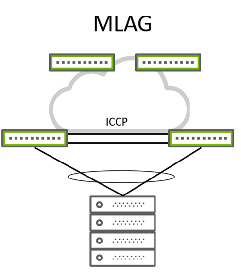 Figure 1. Typical MLAG wiring
With MLAG (Figure 1), a client device can be a server or hypervisor, and a switch or router forms a classical link aggregation group (LAG) that typically bonds two physical links into a single logical link. On the other side of these links, you typically have two switches, which these links connect to. From an LACP point of view, these two switches act like a single switch with the same LACP system ID. This makes MLAG work from a server perspective.
However, for the two MLAG participating switches, things are a bit more complex. Because they require state and MAC synchronization between them, a heartbeat is also needed to prevent split-brain situations and traffic flow over peer links in case one of the participating switches loses its uplink. This peer link makes the entire design non-standard, complex, and error-prone (not fitting in a CLOS leaf and spine architecture).
There are efforts to make state and MAC synchronization standard. RFC7275 focuses on solving this problem and addressing it with a new protocol called Inter-Chassis Control Protocol (ICCP). However, different vendors still implement various flavors of RFC7275 and end up with the same issues. This MLAG solution solved the multihoming problem in a limited scope.
While the future of MLAG is bleak, there’s a more flexible and technically superior multihoming solution: EVPN multihoming (also called EVPN-LAG or ESI-LAG).
Benefits of EVPN multihoming
Multihoming is no stranger to the ISP world and initially came along as a WAN technology. However, it became clear that modern data centers require their own way of implementing multihoming.
Coincidentally, EVPN itself was first introduced as a WAN technology, then evolved into a data center technology. EVPN adopted multihoming functionality rather quickly. With RFC7432, EVPN-MH uses a new addressing field called the Ethernet Segment Identifier (ESI). This fundamental building block that makes EVPN-MH work is used everywhere across the fabric, as far as type-1 and type-4 routes are propagated. ESI is a 10-byte field that specifies a specific multihomed segment.
Let’s talk about what is under the hood of EVPN-MH, route types, and what makes it attractive compared to legacy and proprietary MLAG.
EVPN-MH uses Border Gateway Protocol (BGP) as the control plane in contrast to ICCP, which MLAG uses. And, EVPN-MH uses several different types of EVPN route types as per RFC7432.
EVPN Route Type-1
EVPN Type-1 Route functions can be listed as mass withdrawal, aliasing, and load sharing (Figure 2).
Mass withdrawal
Mass withdrawal makes sure that if a particular link goes down on an ES, you can withdraw all dependent MAC addresses connected to that particular link. This way, you achieve fast convergence by sending a mass withdrawal instead of one by one for each MAC. This assumes that a hypervisor is connected to that ES with many VMs, over the same VLAN, or over hundreds of VLANs.
Aliasing and load balancing
Aliasing and load balancing makes sure that downstream traffic towards an ES is load-balanced across ES member switches, also known as EVI. This way, the ES member switches can receive traffic from other switches in the fabric in a load-shared manner, regardless of whether they are advertising that particular MAC behind their ES.
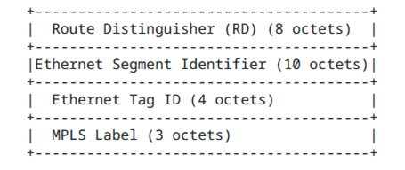 Figure 2. EVPN Ethernet Auto-Discovery route Type-1 frame format
EVPN Route Type-2
Type-2 (MAC/IP) routes are advertised by the same ES member leafs and they include the ESI value for each MAC attached to this Ethernet Segment (Figure 3).
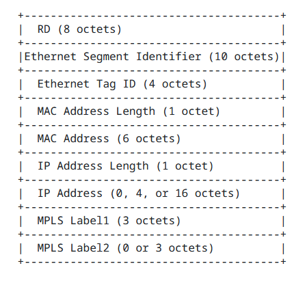 Figure 3. EVPN MAC/IP Advertisement Route type-2 frame format
Type-2 routes are not part of the EVPN-MH setup, however, they make use of ESI information when it’s present for a specific destination MAC.
EVPN Route Type-4
EVPN Type-4 routes are used for election of designated forwarder (DF) and autodiscovery of multihomed ES (Figure 4).
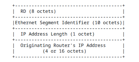 Figure 4. EVPN Ethernet Segment Route type-4 frame format
EVPN type-1 and type-4 routes make EVPN-MH work and provide standards-based interoperability. Type-4 routes are imported by only routers or leafs that participate in that particular ES. Other routers or leafs in the fabric that don’t participate in that ES don’t import type-4 routes. Type-4 routes are used for DF elections to select where to send local BUM traffic.As BUM traffic has to be flooded across the network, in multihomed scenarios, only the DF is responsible for sending BUM traffic to its clients (such as multihomed servers).
Typical EVPN-MH topology can be seen in Figure 5.
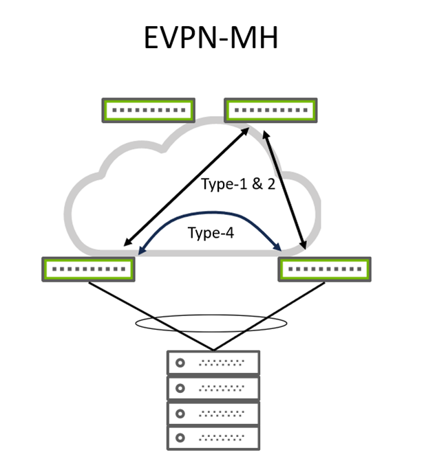 Figure 5. Typical EVPN-MH wiring
Advantages of EVPN-MH:
- Control-plane based MAC and state synchronization
- Standards-based, BGP EVPN route types, and interoperability
- Fabric-wide-route distribution of multihomed connections
- Fast convergence, withdrawal
- Capable of 2+ multihoming
- No need for physical peer link connectivity
- Future proof
- Scalable with BGP
Conclusion
EVPN-MH is a future-proof technology that uses BGP as its control plane. Its standards-based architecture, ability to provide multihoming to end hosts with more than two gateways, and active-active load balancing make it an attractive de facto solution in modern data center networks. Also, removing the need for a peer link between leafs fits EVPN-MH into the Clos architecture perfectly, reducing cost and complexity.
I recommend using EVPN-MH for data centers with EVPN as the control plane, which will soon substitute all MLAG deployments in the field. Existing networks can stay with MLAG as they are already operational. However, new deployments and designs should certainly be based on EVPN-MH.
For more resources, check out the NVIDIA Cumulus Linux Multi-Chassis Link Aggregation–MLAG configuration guide.
Source:: NVIDIA
